1-800-868-2450
My Account | Cart | Checkout
Choosing the right Oil Filled Transformer is not simply a matter of comparing rated power and purchase prices. The correct choice must match the electrical network, installation environment, expected load, and long-term maintenance plan. A transformer working beside a coastal substation faces different risks from one installed inside a dry industrial plant. Salt air, dust, heat, humidity, and limited ventilation can gradually affect performance.
Start with the actual load profile, not only the nameplate demand. Record peak loads, daily operating hours, motor starting currents, and possible future expansion. A unit that appears economical today may operate too close to its limit tomorrow. Check voltage ratios, frequency, impedance, vector group, tap-changer requirements, and acceptable losses. These details influence voltage stability and protection coordination. Small errors matter.
The insulating oil also deserves careful attention. Ask for fluid specifications, fire-safety information, factory test reports, and clear maintenance instructions. Mineral oil is common, but alternative fluids may suit locations with stricter fire-risk requirements. Cooling methods, such as ONAN or ONAF, should fit the site’s heat conditions and operating pattern. Review applicable IEC or IEEE requirements with a qualified engineer, because local rules and utility standards may differ.
A reliable selection process includes supplier experience, inspection records, warranty terms, spare-parts access, and realistic service support. Do not trust impressive brochures alone. Request verified test results, including insulation, ratio, losses, and temperature-rise tests. Field experience often reveals problems that a specification sheet misses. A perfect selection rarely exists. The practical goal is a safe, efficient, serviceable Oil Filled Transformer that remains dependable throughout its working life. Recheck every assumption before approval.
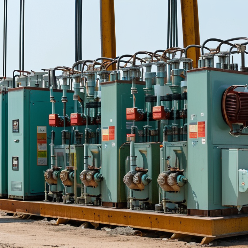
How to Choose the Right Oil Filled Transformer?
Choosing an oil filled transformer starts with defining the electrical load, voltage, and power requirements. Do not estimate from the building’s floor area. Create a load schedule listing lighting, motors, heaters, control systems, and future equipment. Record each device’s rated voltage, current, phase, and power factor. Motors may draw several times their running current during startup. That brief surge can affect transformer sizing.
Calculate the expected demand in kVA, not only kilowatts. Use the formula kVA = kW ÷ power factor. Check whether the supply is single-phase or three-phase. Confirm the primary and secondary voltages from actual equipment nameplates. A mismatch can damage equipment or create unstable operation. Include continuous loads, intermittent loads, and reasonable expansion capacity. Oversizing also deserves caution. It can increase cost and reduce efficiency under light loading.
Tips: Measure real operating current when possible. Review utility data and protection settings. Ask a qualified electrical engineer to verify the calculations. In field assessments, one overlooked motor has often changed the required capacity. I still recheck every load schedule. Assumptions can be wrong. Consider ambient temperature, installation altitude, cable length, and available fault current. These details influence cooling, voltage drop, and protection coordination. Keep the final design supported by test records, calculation sheets, and applicable electrical standards.
Define the electrical load, voltage, and power requirements before selecting the transformer rating.
The chart converts connected load from kW to apparent power in kVA using the estimated power factor, then adds a 25% capacity margin. Select a standard transformer rating above the calculated requirement. The example assumes an 11 kV primary supply and a 400 V secondary supply; actual voltage, load diversity, motor starting current, ambient temperature, and future expansion should be verified before final selection.
Choosing the right oil-filled transformer requires more than checking its rated capacity.
Distribution transformers suit local networks and moderate loads, while power transformers support substations and heavier operating demands. A conservator tank can accommodate oil expansion, but sealed designs reduce exposure to moisture and oxygen. Neither option is automatically better.
Cooling method affects temperature rise, efficiency, and maintenance. ONAN cooling uses natural oil circulation and natural air movement, making it simple and quiet. ONAF adds fans for higher loads, but fans require controls, testing, and replacement planning.
In dusty rooms, cooling performance may decline faster than expected. That detail is easy to overlook.
Tips:
Match the transformer to the real load profile, not only the nameplate rating. Compare mineral oil with ester fluids when fire safety or environmental conditions matter. Check cellulose insulation quality, moisture levels, oil testing access, and expected service temperature. Keep clearance around radiators. Ask for test records. A spreadsheet helps, but it cannot replace a site inspection. The perfect selection rarely exists; a slightly conservative design may cost more initially, yet reduce thermal stress and unplanned downtime. Conversely, oversizing can increase losses during lightly loaded hours. A careful engineer should question both extremes.
Choosing the right oil-filled transformer starts with the actual load profile, not nameplate capacity alone.
Efficiency depends on average loading, peak demand, and operating temperature. Compare no-load and load losses in the technical data. A lightly loaded unit can waste energy continuously. Size it near expected demand, while allowing sensible future growth. Measure harmonics when variable-speed drives or nonlinear loads are present. Otherwise, heat may rise unexpectedly. Look for tested efficiency figures, not broad marketing claims.
Safety features deserve equal attention. Confirm pressure-relief devices, oil-level indicators, temperature alarms, and dependable grounding. The enclosure should resist corrosion and prevent accidental contact with energized parts. Ask for verified routine and type-test records. Fire risk also matters. Check oil containment, separation distances, and local fire requirements with a qualified engineer. A sealed design may reduce contamination, but it does not remove inspection duties. Small leaks are easy to ignore. That is a costly habit.
Installation conditions can change performance. Check altitude, ambient temperature, humidity, ventilation, and floor space before ordering. The foundation must carry the filled weight and remain level. Provide access for lifting, cable termination, sampling, and maintenance. Keep radiators unobstructed; trapped heat shortens insulation life. Confirm cable-bending space and earthing connections on the drawings. Commissioning should include torque checks, insulation tests, oil inspection, and alarm verification. I would also revisit the load estimate after several months. Early assumptions are often wrong, especially in expanding facilities.
Choosing an oil-filled transformer starts with standards, not price. IEC 60076 defines core design, testing, and performance requirements, while IEEE C57.104 guides dissolved-gas analysis. Confirm the supplier’s test records, oil specification, insulation class, and temperature-rise limits. A compliant unit is easier to inspect and defend during an incident.
Maintenance changes the ownership equation. Ask how often oil sampling, leak checks, bushing inspections, and thermal scans are required. CIGRE Technical Brochure 642 identifies bushings, windings, and tap changers among major power-transformer failure contributors. That evidence supports condition-based maintenance, but field conditions still matter. Dust, humidity, overloads, and poor ventilation can shorten service life. Measure the heat. Do not trust a clean nameplate alone.
Energy losses deserve a full-cost calculation. The U.S. Department of Energy estimated that its 2024 distribution-transformer efficiency standards could save about 3.6 quadrillion British thermal units over 30 years and deliver roughly 15.8 billion dollars in net benefits. Compare purchase price, no-load losses, load losses, oil testing, outage risk, disposal, and expected life. A cheaper transformer may cost more during lightly loaded years. That point is easy to miss. I would also challenge optimistic maintenance forecasts; they often assume perfect access, stable loads, and immediate repairs. Real sites are less cooperative.
How to Choose the Right Oil Filled Transformer?
Selecting a reliable manufacturer begins with evidence, not attractive brochures. Ask for factory certificates, quality-control procedures, and recent routine test reports. A trustworthy supplier should explain each result clearly, without hiding unusual readings.
Confirm the technical specification before discussing price. Record the rated capacity in kVA, primary and secondary voltages, frequency, impedance, and vector group. Check the tap range, cooling method, insulation level, temperature rise, and permitted installation altitude. The enclosure must suit the environment, especially where dust, moisture, or salt air is present. Specify the transformer oil type and require documented oil-quality testing. Review losses carefully, because a cheaper purchase can create higher operating costs for years.
Small details matter.
Request drawings showing dimensions, lifting points, cable entries, and earthing terminals. Confirm applicable standards and ask whether independent inspection is available before shipment. Factory acceptance testing should cover winding resistance, ratio, insulation, leakage, and no-load losses. Keep the test records with the equipment history.
I once focused too heavily on capacity and overlooked the available maintenance space. That mistake could have complicated future oil sampling and bushing inspection. Manufacturer references can reveal similar problems before delivery. However, references are not proof by themselves. Compare lead times, spare-parts support, warranty conditions, and response procedures in writing. Technical discussions should include your actual load profile, not only the nameplate rating. A careful manufacturer may challenge your assumptions, and that can be useful. My own selection process still improves when field conditions are measured instead of guessed.
| Selection Criterion | Recommended Technical Specification or Checkpoint | Why It Matters | What to Confirm with the Manufacturer |
|---|---|---|---|
| Applicable Design Standard | IEC 60076 series or IEEE C57 standards, according to the project location and utility requirements. | The applicable standard defines design, insulation, temperature-rise, testing, and performance requirements. | Request the exact standard edition, compliance statement, design drawings, and routine test reports. |
| Rated Power | Select the required kVA or MVA rating based on the calculated maximum demand, diversity, motor starting current, and future load growth. | An undersized transformer may overheat or suffer voltage drop, while excessive oversizing can increase purchase and no-load operating costs. | Confirm the continuous rating, overload capability, ambient conditions, and the calculation used for the selected capacity. |
| Primary and Secondary Voltage | Specify the exact system voltages, such as 11 kV / 0.4 kV or another project-defined combination, including voltage tolerances. | Correct voltage matching is essential for safe operation, equipment compatibility, and acceptable secondary voltage. | Verify rated voltage, highest voltage for equipment, insulation level, neutral arrangement, and connection to the site network. |
| Frequency and Phase | Normally 50 Hz or 60 Hz, with single-phase or three-phase construction as required by the electrical system. | Frequency and phase affect magnetic flux, losses, impedance, protection settings, and compatibility with connected loads. | Confirm rated frequency, phase configuration, phase sequence, and suitability for the local utility supply. |
| Vector Group and Neutral | Choose the required vector group, such as Dyn11, and specify whether the low-voltage neutral is brought out and grounded. | Vector group determines phase displacement and affects parallel operation, fault behavior, and grounding arrangements. | Confirm the vector group, neutral terminal size, grounding method, phase displacement, and parallel-operation requirements. |
| Percentage Impedance | A commonly specified distribution-transformer range is approximately 4% to 6%, subject to the fault-current and voltage-drop study. | Impedance influences short-circuit current, voltage regulation, load sharing, and protection coordination. | Request guaranteed impedance tolerance, positive and zero-sequence impedance where applicable, and short-circuit withstand data. |
| Energy Efficiency | Evaluate guaranteed no-load loss, load loss, total loss at the specified loading point, and compliance with applicable efficiency regulations. | Transformers remain energized for long periods, so no-load and load losses have a significant effect on lifetime operating cost. | Ask for guaranteed loss values, measurement tolerances, loss evaluation conditions, and the calculation of total cost of ownership. |
| Temperature Rise and Cooling | Specify the permitted top-oil and winding temperature rise according to the selected standard and site ambient conditions; common cooling designations include ONAN. | Temperature directly affects insulation aging, service life, overload capability, and reliability. | Confirm maximum ambient temperature, altitude correction, cooling mode, temperature-rise test results, and thermal monitoring provisions. |
| Insulating Liquid | Use a suitable mineral insulating oil or approved alternative fluid with appropriate dielectric strength, oxidation stability, and environmental properties. | The liquid provides insulation and transfers heat; its quality affects fire risk, maintenance, and long-term dielectric performance. | Confirm liquid type, applicable fluid standard, inhibited or uninhibited formulation, fluid test results, and environmental documentation. |
| Tank and Sealing System | Select a sealed-tank or conservator design with adequate mechanical strength, corrosion protection, and leak-resistant joints. | Moisture ingress and oil leakage reduce insulation performance and can shorten transformer service life. | Check pressure or vacuum testing, coating system, gasket materials, tank thickness, leak-test records, and corrosion category suitability. |
| Tap-Changer Arrangement | Use an off-circuit tap changer for de-energized voltage adjustment, or an on-load tap changer where voltage must be regulated while energized. | Tap selection helps compensate for supply-voltage variation and maintain the required secondary voltage. | Confirm tap range, typical options such as ±2 × 2.5% or ±5%, operating mechanism, position indication, and interlocking requirements. |
| Insulation and Lightning Protection | Define rated insulation levels, power-frequency withstand voltage, lightning impulse withstand voltage, and surge-arrester coordination. | Proper insulation coordination reduces the risk of failure caused by lightning, switching surges, and network disturbances. | Request insulation-level schedules, impulse-test records where applicable, bushing ratings, creepage distance, and surge-protection recommendations. |
| Accessories and Monitoring | Typical accessories may include oil-level indicator, pressure-relief device, thermometer, drain valve, lifting lugs, earthing terminals, and temperature alarm contacts. | Correct accessories support safe installation, condition monitoring, maintenance, and rapid fault response. | Confirm the accessory list, alarm and trip contacts, control voltage, wiring diagram, terminal-box rating, and spare-parts availability. |
| Routine and Type Testing | Routine tests commonly include winding resistance, ratio and phase displacement, impedance and load loss, no-load loss and current, dielectric tests, and leak checks. | Documented testing verifies that the manufactured unit conforms to the approved design and guaranteed performance. | Require signed test reports, calibration certificates, inspection and test plans, witness-test options, and independent inspection arrangements. |
| Manufacturer Reliability | Evaluate proven experience with comparable voltage and power ratings, documented quality systems, production capability, and after-sales support. | A technically suitable design can still create project risk if manufacturing controls, delivery capability, or service support are inadequate. | Review reference installations without relying only on marketing claims, quality certificates, warranty terms, lead time, service response, and spare-parts support. |
| Installation Environment | Specify indoor or outdoor use, altitude, ambient temperature, humidity, pollution level, seismic conditions, enclosure requirements, and available space. | Environmental conditions affect cooling, insulation performance, corrosion protection, dimensions, and installation safety. | Confirm all site data, derating requirements, cable-entry arrangement, foundation loads, sound limits, fire-safety requirements, and maintenance clearances. |
| Documentation and Acceptance | Require an approved datasheet, dimensional drawing, nameplate, wiring diagram, installation manual, operation manual, certificates, and final test dossier. | Complete documentation supports approval, installation, commissioning, maintenance, and future replacement planning. | Agree on the document-submittal schedule, approval procedure, factory acceptance test requirements, warranty coverage, and final acceptance criteria. |
Note: Final ratings and guaranteed values must be determined from the project load study, utility requirements, site conditions, and the applicable electrical standard. The ranges shown are general engineering reference points rather than a substitute for a project-specific specification.
I&M Industrials Inc.
10 Akron Drive
Greenville SC 29605
Phone: 864-277-2450
GSA Number – GS07F0379Y