1-800-868-2450
My Account | Cart | Checkout
Choosing the right Wired Push Button is a small decision with serious operational consequences. A failed switch can stop a conveyor, delay maintenance, or create confusion during an emergency. The International Federation of Robotics reported 541,302 industrial robots were installed worldwide in 2023. That growth reflects increasingly automated workplaces, where dependable human-machine controls still matter.
The selection process should begin with the application, not the product photograph. Check the required voltage, current, contact arrangement, actuator style, and mechanical life. Confirm whether the button needs momentary or maintained action. Then examine the enclosure rating, operating temperature, vibration exposure, and cable-entry method. IEC 60947-5-1 provides important requirements for low-voltage control-circuit devices. NEMA enclosure guidance also helps engineers match protection levels to dust, water, and industrial conditions. A shiny metal button may look robust. It may not survive cutting fluid or repeated impact.
Field experience suggests that wiring details often receive too little attention. Terminal access, cable length, labeling, and replacement time can affect total ownership cost. Independent market research from Grand View Research identifies industrial automation as a rapidly expanding market, increasing pressure on manufacturers to build reliable, maintainable control panels. However, market growth does not guarantee product quality. Datasheets can omit practical weaknesses. The best choice combines verified ratings, supplier traceability, tested compatibility, and clear installation instructions. Leave room for doubt. Test the button under realistic load conditions before approving a full installation. This guide explains how to compare these factors and select a Wired Push Button that fits both the machine and the people operating it.
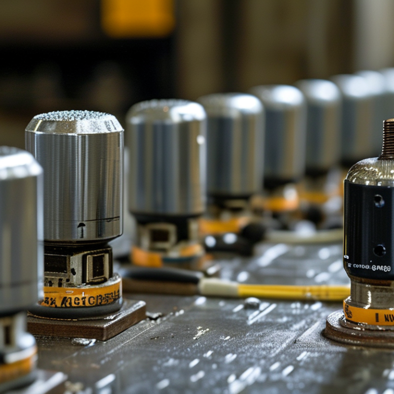
A wired push button converts physical pressure into an electrical command. Its operating mechanism matters more than its appearance.
Momentary buttons return after release. Maintained buttons stay in position. Emergency-stop devices usually use a latching action and require deliberate resetting. Choose the mechanism based on the control sequence, not habit.
Contact blocks also shape performance. Normally open contacts close when pressed. Normally closed contacts open during activation and can support fault detection. A mechanical contact suits many low-speed circuits. A gold-plated contact may perform better with low-current signals. IEC 60947-5-1 defines key requirements for low-voltage control devices. It remains a useful reference during selection. Grand View Research valued the industrial automation market at USD 191.89 billion in 2021. Its report projected a 10.5% compound annual growth rate through 2030. More automation means more small control decisions at the machine interface. A button is simple, but its failure can stop a process.
Tips: Match voltage, current, enclosure rating, and contact configuration. Check the wiring diagram twice. Test gloves, moisture, dust, and repeated impacts. I often find that a “perfect” button feels wrong after installation. Travel may be too long. The actuator may be too small. Leave room for real operators, not only catalog measurements. Check IEC 60204-1 and applicable local requirements before commissioning.
Matching a wired push button to your electrical requirements begins with the circuit, not the appearance. Check the rated voltage and current for the actual load. A button marked for low-power control may fail when switching a motor directly. Motors create inrush current, which can exceed their running current several times. Use a relay or contactor when the load demands it. I once selected a button by its continuous rating alone. That was not enough.
Confirm whether the circuit needs normally open, normally closed, or changeover contacts. Choose momentary action for start commands and maintained action for simple on-off control. Check the contact material, terminal style, wire size, and expected electrical cycles. For dusty workshops or outdoor panels, review the IP rating carefully. Also consider the enclosure thickness and the button’s mounting diameter. A perfect electrical match can still become a poor installation choice.
Tips: Read the complete datasheet, not only the product label. Separate the button’s switching rating from its mechanical life. Test the circuit with the intended power supply and load. Leave a safety margin, especially with inductive equipment. If the specification seems unclear, stop and verify it with a qualified electrician. Small details matter. They are easy to overlook.
Installation method should match the panel, cable route, and maintenance routine. Panel-mounted buttons suit control cabinets with prepared cutouts. Surface-mounted units work better on walls, machines, or uneven enclosures. For retrofit projects, measure the opening carefully. A small mismatch can weaken the seal. Leave enough cable length for inspection and replacement. Too little slack causes stress at the terminals.
Material choice affects service life. Stainless steel handles frequent contact, cleaning, and outdoor exposure. Polycarbonate and nylon can reduce weight and cost. However, plastic may become brittle under sunlight, heat, or impact. Check the operating temperature and chemical resistance, not only the appearance. The actuator should move smoothly and return without sticking. A clear tactile response matters.
Environmental protection needs practical verification. Look for an IP rating tested under IEC 60529 conditions. IP65 may resist dust and water jets, while IP67 supports temporary immersion. These ratings do not guarantee resistance to oil, salt spray, or strong detergents. Select a sealed cable gland and inspect the gasket during installation. I once saw a well-rated button fail because the cable entry was tightened unevenly. The enclosure looked secure. It was not. Review test reports, terminal quality, and maintenance access before approval. A neglected gasket can undo careful component selection.
How to Choose the Right Wired Push Button?
A wired push button should match the control circuit, not just the panel opening. Check its rated voltage, current, contact arrangement, and terminal type. A button designed for low-voltage signaling may fail in a higher-power circuit. Confirm the wire size and connector fit before installation. I once assumed that matching the hole diameter was enough. That assumption was wrong. The button also needs suitable insulation and protection against dust, moisture, vibration, and accidental impact.
Tips: Read the technical datasheet carefully. Verify normally open or normally closed contacts. Check the operating temperature range. Look for recognized safety testing, clear markings, and installation instructions. Certification alone is not a substitute for correct wiring.
Expected service life depends on mechanical cycles and electrical load. A button used several hundred times daily will age faster than one used occasionally. Switching an inductive load can also shorten contact life. Use a relay when the button should only send a control signal. Inspect for loose terminals, cracked housing, sticking movement, or discoloration. These small signs matter. Choose a model with a service rating above your expected workload, but avoid trusting impressive cycle numbers without checking test conditions. Real environments are rarely as clean as laboratory tests.
| Selection Dimension | What to Check | Typical Reference Data | Recommended Decision |
|---|---|---|---|
| Contact Configuration | Confirm whether the circuit needs normally open (NO), normally closed (NC), or changeover contacts. | NO is commonly used to start or trigger a circuit. NC is commonly used for stop, interlock, or safety-loop functions. | Match the circuit diagram |
| Rated Voltage | Compare the button's AC or DC voltage rating with the actual system voltage. | Typical control circuits may use 12 VDC, 24 VDC, 120 VAC, or 230 VAC. AC and DC ratings are not interchangeable. | Choose an equal or higher rating |
| Rated Current and Load Type | Check steady-state current, inrush current, motor or lamp loads, and whether a relay or contactor is required. | Resistive-load ratings are often higher than motor, inductive, capacitive, or tungsten-load ratings. | Use the correct load category |
| Electrical Safety Standard | Review the applicable product and installation requirements for the target market and equipment category. | Common references include IEC 60947-5-1 for low-voltage control-circuit devices and IEC 61058-1 for certain appliance switches. | Verify the marking and declaration |
| Ingress Protection | Assess exposure to dust, water jets, condensation, cleaning fluids, and accidental splashing. | IP40 provides limited object protection; IP65 is dust-tight and protected against water jets; IP67 includes temporary immersion protection when correctly installed. | Select the required IP level |
| Operating Environment | Check ambient temperature, humidity, vibration, shock, corrosion, and chemical exposure. | Many industrial push buttons are specified around −20 °C to +55 °C, but the approved range varies by construction and sealing. | Use the manufacturer's tested range |
| Terminal and Wire Compatibility | Match screw, solder, quick-connect, or spring-terminal construction with the wiring method and conductor size. | Common control wiring uses approximately 0.5–1.5 mm² conductors, but terminal limits must be checked on the product specification. | Confirm terminal size and torque |
| Panel Cutout and Mounting | Measure the panel hole, mounting depth, thread or retaining nut, and available rear clearance. | Common panel cutouts include approximately 16 mm, 19 mm, 22 mm, and 30 mm, depending on the button design. | Match the exact dimensions |
| Actuator Type | Choose between momentary, maintained, latching, illuminated, guarded, or emergency-stop-style operation. | Momentary buttons return after release; maintained buttons remain in their selected state until operated again. | Match the required operating logic |
| Mechanical Service Life | Check the number of no-load operating cycles and the test conditions used for the rating. | Typical general-purpose push buttons may be rated from about 100,000 to 1,000,000 mechanical cycles. | Allow a practical safety margin |
| Electrical Service Life | Evaluate contact wear under the actual voltage, current, load type, switching frequency, and duty cycle. | Electrical life is usually lower than mechanical life, especially with inductive or high-inrush loads. | Use a relay or contactor for demanding loads |
| Switching Frequency | Estimate operations per hour, day, and year, then compare the result with the specified life. | At 20 operations per hour for 8 hours per day and 250 working days per year, usage is approximately 40,000 cycles per year. | Calculate expected annual cycles |
| Contact Material and Bounce | Consider contact resistance, signal stability, switching speed, and the sensitivity of the connected controller. | Mechanical contacts can produce contact bounce lasting several milliseconds; PLC or microcontroller inputs may require filtering or debounce logic. | Provide suitable input filtering |
| Flammability and Insulation | Check insulation voltage, dielectric strength, creepage and clearance, and enclosure-material flammability where required. | Requirements depend on working voltage, pollution level, overvoltage category, and the applicable equipment standard. | Follow the equipment safety assessment |
| Maintenance and Replacement | Determine whether contacts, lamps, seals, terminals, or the complete unit can be replaced economically. | Replaceable contact blocks can reduce downtime; sealed constructions generally reduce maintenance in dusty or wet environments. | Plan for the full operating life |
In control panel work, I check the operating environment before comparing prices. A button near wash areas needs suitable ingress protection. A dusty workshop may require a sealed housing and a strong actuator. Confirm the contact rating, terminal type, wire size, and expected switching cycles. The panel cutout must also match. A small mismatch can delay installation.
Purchase cost is only one part of the decision. Add wiring time, mounting hardware, testing, and possible production downtime. A cheaper button may use weaker contacts or less durable springs. That difference matters when operators press it hundreds of times daily. I once chose a low-cost option for a light-duty panel. The saving disappeared after repeated contact faults. That shortcut was expensive.
Maintenance needs should be visible before purchase. Look for clear terminal markings and replaceable contact blocks. These details reduce inspection time and wiring mistakes. Check the manufacturer’s technical data, safety ratings, and service instructions from a reliable source. During routine maintenance, inspect loose terminals, cracked covers, dust buildup, and inconsistent response. A continuity test can reveal wear before failure occurs. Still, not every application needs the most rugged model. Over-specifying equipment increases cost without adding useful protection. Review actual conditions, user habits, and access for repairs. My own estimates are sometimes too optimistic, especially when downtime costs are ignored.
I&M Industrials Inc.
10 Akron Drive
Greenville SC 29605
Phone: 864-277-2450
GSA Number – GS07F0379Y